How to Build a News App with Svelte

Original Source: https://www.sitepoint.com/svelte-news-app-build/?utm_source=rss

How to Build a News App with Svelte

Svelte is a new JavaScript UI library that’s similar in many ways to modern UI libraries like React. One important difference is that it doesn’t use the concept of a virtual DOM.

In this tutorial, we’ll be introducing Svelte by building a news application inspired by the Daily Planet, a fictional newspaper from the Superman world.

About Svelte

Svelte makes use of a new approach to building users interfaces. Instead of doing the necessary work in the browser, Svelte shifts that work to a compile-time phase that happens on the development machine when you’re building your app.

In a nutshell, this is how Svelte works (as stated in the official blog):

Svelte runs at build time, converting your components into highly efficient imperative code that surgically updates the DOM. As a result, you’re able to write ambitious applications with excellent performance characteristics.

Svelte is faster than the most powerful frameworks (React, Vue and Angular) because it doesn’t use a virtual DOM and surgically updates only the parts that change.

We’ll be learning about the basic concepts like Svelte components and how to fetch and iterate over arrays of data. We’ll also learn how to initialize a Svelte project, run a local development server and build the final bundle.

Prerequisites

You need to have a few prerequisites, so you can follow this tutorial comfortably, such as:

Familiarity with HTML, CSS, and JavaScript (ES6+),
Node.js and npm installed on your development machine.

Node.js can be easily installed from the official website or you can also use NVM for easily installing and managing multiple versions of Node in your system.

We’ll be using a JSON API as a source of the news for our app, so you need to get an API key by simply creating an account for free and taking note of your API key.

Getting Started

Now, let’s start building our Daily Planet news application by using the degit tool for generating Svelte projects.

You can either install degit globally on your system or use the npx tool to execute it from npm. Open a new terminal and run the following command:

npx degit sveltejs/template dailyplanetnews

Next, navigate inside your project’s folder and run the development server using the following commands:

cd dailyplanetnews
npm run dev

Your dev server will be listening from the http://localhost:5000 address. If you do any changes, they’ll be rebuilt and live-reloaded into your running app.

Open the main.js file of your project, and you should find the following code:

import App from ‘./App.svelte’;

const app = new App({
target: document.body,
props: {
name: ‘world’
}
});

export default app;

This is where the Svelte app is bootstrapped by creating and exporting an instance of the root component, conventionally called App. The component takes an object with a target and props attributes.

The target contains the DOM element where the component will be mounted, and props contains the properties that we want to pass to the App component. In this case, it’s just a name with the world value.

Open the App.svelte file, and you should find the following code:

<script>
export let name;
</script>

<style>
h1 {
color: purple;
}
</style>

<h1>Hello {name}!</h1>

This is the root component of our application. All the other components will be children of App.

Components in Svelte use the .svelte extension for source files, which contain all the JavaScript, styles and markup for a component.

The export let name; syntax creates a component prop called name. We use variable interpolation—{…}—to display the value passed via the name prop.

You can simply use plain old JavaScript, CSS, and HTML that you are familiar with to create Svelte components. Svelte also adds some template syntax to HTML for variable interpolation and looping through lists of data, etc.

Since this is a small app, we can simply implement the required functionality in the App component.

In the <script> tag, import the onMount() method from “svelte” and define the API_KEY, articles, and URL variables which will hold the news API key, the fetched news articles and the endpoint that provides data:

<script>
export let name;

import { onMount } from “svelte”;

const API_KEY = “<YOUR_API_KEY_HERE>”;
const URL = `https://newsapi.org/v2/everything?q=comics&sortBy=publishedAt&apiKey=${API_KEY}`;
let articles = [];

</script>

onMount is a lifecycle method. Here’s what the official tutorial says about that:

Every component has a lifecycle that starts when it is created and ends when it is destroyed. There are a handful of functions that allow you to run code at key moments during that lifecycle. The one you’ll use most frequently is onMount, which runs after the component is first rendered to the DOM.

Next, let’s use the fetch API to fetch data from the news endpoint and store the articles in the articles variable when the component is mounted in the DOM:

<script>
// […]

onMount(async function() {
const response = await fetch(URL);
const json = await response.json();
articles = json[“articles”];
});
</script>

Since the fetch() method returns a JavaScript Promise, we can use the async/await syntax to make the code look synchronous and eliminate callbacks.

The post How to Build a News App with Svelte appeared first on SitePoint.

These fake AirPods are utterly ludicrous

Original Source: http://feedproxy.google.com/~r/CreativeBloq/~3/xhZSkN2t6R4/fake-airpods

Apple AirPods have become the absolute must-have accessory for iPhone, iPad and iPod since their launch in 2016. They have a lot of brilliant tech packed into them, and although they looked a bit weird when they first came out, it's now impossible to walk down the street without passing loads of people with those telltale AirPod arms hanging out of their ears.

AirPods aren't without their drawbacks, though. For starters, they're expensive; even if you search out the best Apple AirPod deals, you're talking over £150 for a pair, and that's before you've factored in the essential wireless charging case. That's a lot to pay for something that you're more likely to lose than you are a traditional pair of wired earphones.

Apple Black Friday deals: What to expect in 2019

And of course, you need an Apple device to go with them; no AirPods for you, Android owners. Amazon's just announced its own Echo Buds, which appear to be a strong AirPod alternative with many similar features at a less hefty price, but do they look as cool as actual AirPods? 'Cool' is very much a subjective thing, but we feel that many would think that no, they do not.

Fake AirPods: ASOS site

From a distance, who’s going to know?

However, if you want that distinctive, "Hey, look at me, I've got some AirPods!" look, here's ASOS with a solution that'll give you instant street cred at a tiny fraction of the price. It's launched its own fake AirPods – that's ASOS DESIGN faux headphone ear piece in silver tone to you – and they're absolutely ideal for looking like you're wearing AirPods. At least from a distance.

Like real AirPods, they're not quite perfect. For one thing, they're not that unmistakable AirPod white. Instead they're 100 per cent zinc with a silver-tone finish, which isn't likely to fool anyone, but you could always claim that you have a cousin who works at Apple who gave you a secret silver pair that isn't even going to be out until next year. Definitely worth a shot.

Fake AirPods: close-up

No, they don’t work. And yeah, you only get one.

Oh, and for another thing, they don't actually work. All they're for is making it look a bit like you're wearing AirPods. You may laugh, but we're absolutely certain there's a market for this. Admittedly, though, if being able to listen to music or podcasts is a deal-breaker for you then you might want to pass on these.

And for a third and final thing, we think you only get one faux headphone ear piece. So if you want to achieve the full effect then you'll probably have to order two of them. But at £6 a shot you're not exactly going to break the bank; you could buy at least 25 of them for what you'd pay for some actual functional AirPods!

ASOS, we salute your chutzpah. Please send us some.

Related articles:

The 10 most beautiful Apple products (and the 5 ugliest)Apple shares how AirPod users personalise their cases – and they look amazing!The 100 greatest Apple creations

Popular Design News of the Week: September 16, 2019 – September 22, 2019

Original Source: https://www.webdesignerdepot.com/2019/09/popular-design-news-of-the-week-september-16-2019-september-22-2019/

Every week users submit a lot of interesting stuff on our sister site Webdesigner News, highlighting great content from around the web that can be of interest to web designers. 

The best way to keep track of all the great stories and news being posted is simply to check out the Webdesigner News site, however, in case you missed some here’s a quick and useful compilation of the most popular designer news that we curated from the past week.

Note that this is only a very small selection of the links that were posted, so don’t miss out and subscribe to our newsletter and follow the site daily for all the news.

Don’t Make the Same Design Fail as the Chicago Bulls Logo


15 Unique Website Layouts


Where to Put Buttons on Forms


Free Collection of Amazing PNG Images


5 Soft Skills Every Product Designer Should Master


Microsoft’s New Font for Devs is Very Aesthetically Pleasing (and Free)


7 CTA Button Design Guidelines


Sticky Positioning with Nothing but CSS (Thanks to CSS Position: Sticky)


Typography Basics: Terminology, Examples, And Infographics


AI UI Pattern Library


Inconsistent Behavior Among Browsers When Clicking on Buttons


(Why) Some HTML is “Optional”


A Love Letter to Personal Websites


Augmented-UI


Dark Mode – Working with Color Systems


‘Intent’ Should Be Every Marketer’s #1 Obsession


Four Tips from my First Year as a UX Developer


UX Design — Question Everything


This Typeface Hides a Secret in Plain Sight. And that’s the Point


10 Best Sites for Vector Illustrations


Storybook 5.2


To do Better Work, Change your Environment


100,000 AI-Generated Faces – Free to Use!


Apparently We’ve been Doing Logos Wrong all this Time


Light Theme, Redeemed


Want more? No problem! Keep track of top design news from around the web with Webdesigner News.

Source

p img {display:inline-block; margin-right:10px;}
.alignleft {float:left;}
p.showcase {clear:both;}
body#browserfriendly p, body#podcast p, div#emailbody p{margin:0;}

Floral Tattoos: Exquisite Black and Grey work by Vanessa Dong

Original Source: http://feedproxy.google.com/~r/abduzeedo/~3/1s41lhuU_c8/floral-tattoos-exquisite-black-and-grey-work-vanessa-dong

Floral Tattoos: Exquisite Black and Grey work by Vanessa Dong

GisMullrSep 27, 2019

Who doesn’t like a beautiful tattoo? I’m talking about those pieces that get your attention. Artworks that make your turn your head to see more of it and check the details. And yes, I’m the kind of person that will start a conversation if I like a tattoo. I know, weird. There are several different styles of tattoo out there. But I’m always drawn to black and grey pieces with beautiful outline and minimal design. And I believe this is why I simply love Vanessa’s work. The tattoos she creates are delicate and beautiful. Masterpieces on skin. The pictures she posts of her work are breathtaking and totally inspiring. She specializes in floral/botanical work and you will see plenty of lines, geometric shapes and negative space on her pieces. Since I’m a sucker for black and grey tattoos and I basically stalk Vanessa on Instagram I decided to get in touch with her and publish some of her work here.

Tattoo artists have the privilege of drawing permanent artworks on people’s skin. And I admire them for that. They listen to your idea and create a concept that will be inked on your skin for good. And oh boy, we all love beautiful timeless tattoo pieces like the ones you will see here. Vanessa is based in Vancouver, BC and she keeps her followers informed about her books on Instagram. So stay tuned to her account if you want to get inked. This is certainly a great excuse to visit Vancouver. 😉

Vanessa is a tattoo artist based in Vancouver, BC. She specializes in floral/botanical black and grey work. She is currently based out of a private studio in East Vancouver. Her work has been featured on Hypebae, Daily Hive Vancouver, Narcity Canada as well as The Mix Society. Vanessa graduated with a Bachelors Degree at Emily Carr University for Communication Design. She did her apprenticeship with Katia at Rainfire Tattoo in 2012-2013. Vanessa loves creating pieces for her clients that are one of a kind.

Exquisite Black and Grey Floral Tattoos by Vanessa DongExquisite Black and Grey Floral Tattoos by Vanessa DongExquisite Black and Grey Floral Tattoos by Vanessa DongExquisite Black and Grey Floral Tattoos by Vanessa DongExquisite Black and Grey Floral Tattoos by Vanessa DongExquisite Black and Grey Floral Tattoos by Vanessa DongExquisite Black and Grey Floral Tattoos by Vanessa DongExquisite Black and Grey Floral Tattoos by Vanessa DongExquisite Black and Grey Floral Tattoos by Vanessa DongExquisite Black and Grey Floral Tattoos by Vanessa DongExquisite Black and Grey Floral Tattoos by Vanessa DongExquisite Black and Grey Floral Tattoos by Vanessa DongExquisite Black and Grey Floral Tattoos by Vanessa DongExquisite Black and Grey Floral Tattoos by Vanessa DongExquisite Black and Grey Floral Tattoos by Vanessa DongExquisite Black and Grey Floral Tattoos by Vanessa DongExquisite Black and Grey Floral Tattoos by Vanessa DongExquisite Black and Grey Floral Tattoos by Vanessa Dong

More links:

tattoosbyvanessa.com
Instagram


Is It Time to Embrace AMP?

Original Source: https://www.webdesignerdepot.com/2019/09/is-it-time-to-embrace-amp/

If you own a website, you should have at least heard the term AMP before. If you haven’t, it’s likely you will hear more about it very soon.

Google’s Accelerated Mobile Pages (AMP) Project has impacted the user experience of millions of mobile web users since its initial launch in 2015. Though primarily used to help website owners build interactive sites that load fast on mobile devices, this project never fails to impress with new and improved features, despite some people’s inability to keep up.

Google recently announced one such feature – Swipe to Visit – in late July of this year. Designed to make it faster and easier than ever for users to view images on mobile devices, this feature also makes accessing those images’ webpages a cinch. All you have to do is search for an image, view the website header preview, and swipe up to be redirected to the website.

This begs the question: Is all of this really necessary?

Of course, Google claims that this is dedicated to improving the user experience, but is having to support projects such as AMP something that should be required by all website owners looking for higher search engine results pages (SERPs)? Or is this just another excuse for Google to control what happens on the Internet?

While there are good arguments on either side, one thing is for sure: Swipe to Visit will change the way people view images and access websites on their mobile devices. You’ll need to decide whether this is something you want to support or not, after you understand the good and the bad of AMP.

Why Is AMP So Important?

When your mobile webpages take forever to load, don’t work right, or force people to zoom, pinch, or rotate their devices, you risk losing a reader instantly. Poorly optimized mobile web design and clunky advertisements ruin the user experience. Google understands this.

In an effort to improve the performance of the mobile web, Google teamed up with Twitter to launch the AMP project. Has it worked?

One study suggests that webpages using AMP load four times faster and use eight times less data compared to traditional, mobile-optimized webpages. Another reveals that AMP can reduce bounce rates by as much as 40%. And let’s not forget about the Events Ticket Center that dropped their page loading times from five to six seconds to a blazing-fast, one-second loading time.

If you’re a publisher that relies on advertisements, you stand to generate up to three times the ad revenue each day and see your ads load five seconds faster by implementing AMP pages.

More than 31 million domains have adopted Google AMP pages since then.

Why Swipe To Visit Is A Good Thing

Whether you’re a fan of Google AMP or not, there’s no denying that the Swipe to Visit feature is a good thing. 

Every person out there with a website is vying for the first page in Google SERPs. However, Google has made it increasingly hard for websites to rank organically, seeing as paid ads and featured snippets are dominating the first page these days.

On tiny mobile devices, this means your website isn’t initially seen much of the time, even if it’s on the first page.

What if we told you that appearing in specialized Google image searches would allow your website to rank higher? Using Google AMP and Swipe to Visit does just that.

Thanks to the unique way people can instantly access your website with a simple swipe, you can not only expect better search rankings, but higher clickthrough rates and lower bounce rates.

Swipe to Visit makes it simple for site visitors to scan images, compare offers, and make better purchasing decisions, all of which are considered by Google to be best practices (and award your higher SERPs). This means that anyone adopting Google AMP pages will automatically enjoy more site traffic from image searches.

The Criticism of AMP

The other side of the coin is that there are a lot of problems associated with AMP.

The truth is that implementing AMP pages is not that easy. Even some websites that do enable Google AMP pages don’t get the results they expected simply because they didn’t do a thorough enough job implementing AMP throughout the entire website.

Criticism from experts centers on the fact that AMP mainly works because it’s so restrictive. Imposing limits is ultimately how AMP reduces load times and bandwidth use. 

Further, a good amount of third-party software doesn’t yet work well with AMP, which can hinder functions like data tracking.

To utilize Google Analytics tracking, AMP requires that every single AMP page uses a unique analytics tag, which can be a burdensome task from the start for large websites, if the tags are added manually.

There are also other things to think about, such as:

There are still branding limitations since JS and CSS aren’t used
AMP only works if users click your AMP-enabled webpage
Even WordPress-specific AMP plugins aren’t always easy to use or compatible with other plugins

Lastly, development has been relatively slow-paced in the AMP world. While 30+ million domains have adopted AMP pages, that’s nowhere near recognizable enough for the average mobile user to realize they’re using (and benefiting from) AMP pages.

Final Thoughts: To Adopt AMP or Not?

The Google AMP project is a great concept with the goal of improving the user experience and helping website owners reap the benefits of said user experiences. When it comes to helpful features like Swipe to Visit, this project becomes even more valuable. However, until AMP pages become more mainstream in mobile results, the time and effort it will take to overhaul your site and implement AMP may not be worth it right now.

In the end, every website owner has a different set of circumstances. This means that enabling AMP on an entire website, on just certain pages, or not at all, might be your best solution.

As the competition continues to stiffen in the online world, it’s going to become more important than ever to consider all the tools available at your disposal, including AMP pages, and determine how these tools can be used to help you achieve your goals.


Featured image via DepositPhotos.

Source

p img {display:inline-block; margin-right:10px;}
.alignleft {float:left;}
p.showcase {clear:both;}
body#browserfriendly p, body#podcast p, div#emailbody p{margin:0;}

5 Popular Freelancing Advice You Should Ignore

Original Source: https://www.hongkiat.com/blog/popular-freelancing-advices/

No matter what your freelance niche is, there’s tons of advice out there that’s considered gospel. Just as there’s popular blogging advice that doesn’t always work,…

Visit hongkiat.com for full content.

Creating Tables In Figma

Original Source: https://www.smashingmagazine.com/2019/09/creating-tables-in-figma/

Creating Tables In Figma

Creating Tables In Figma

Sasha Belichenko

2019-09-25T12:30:59+02:00
2019-09-25T17:05:50+00:00

In this tutorial, we will talk about how tables can be created in Figma by using components and Atomic Design methodology. We will also take a look at the basic elements of the table layout and how components can be included in the component library so that they can become part of the design system you are using.

To make it easy for you, I’ve prepared a mockup example that uses all of the components we need for this tutorial.

To follow along, you will need to have at least some understanding of the basic Figma concepts, its interface, and how to work with Figma components. However, if you’re new to Figma and working with table data, I recommend watching the “Getting Started” video to help you better understand Figma end-to-end, as well as the article “How To Architect A Complex Web Table” that was published not too long ago here on Smashing Magazine.

To simplify the scope of this tutorial, let’s assume that the colors, fonts, and effects already exist as styles in the Figma project you’re about to begin. In terms of Atomic Design, they are atoms. (To learn more, the folks at littleBits wrote a great article on the topic.)

The target audience for this tutorial are designers (UX, UI) who have either already adopted Figma into their workflows or are planning to try Figma in their next design projects but aren’t sure how to get started.

So, without further ado, let’s dig in!

Quick Note: While writing this article, Figma introduced plugins. At the time of publishing, there weren’t any good ones for working with tables, but things might change fast. Who knows, maybe this article will actually help an aspiring Figma plugin developer to create a really neat Figma Tables plugin, or at least, I hope it will. ?

Introduction

Imagine the table as an organism. The table cell is then a molecule which is comprised of individual atoms. In design terms, they’re cell properties.

So, let’s start with the cell. It has three properties:

Background
Border
Content

Now we’ll take a closer look at each one of them.

Background

The background will be a separate component in Figma. The size doesn’t really matter since we can stretch the component as we need, but let’s begin with setting the size to 100×36 pixels.

In this component, add a rectangle of the same size as the component itself. It will be the only object inside the component. We need to attach the rectangle’s borders to the component’s borders by using constraints (set constraints to “Left & Right” and “Top & Bottom” at the right panel in the Constraints section), so that the rectangle stretches automatically to the size of the component.

If you’d like to see this in action, watch this tutorial on how the constraints work in Figma.

The Background Component

The Background Component (the ‘atom’) (Large preview)

The fill color of the rectangle will determine the background color of the cell. Let’s pick the white color for it. I recommend choosing that color from the color styles that are configured at the beginning of the project.

Background color
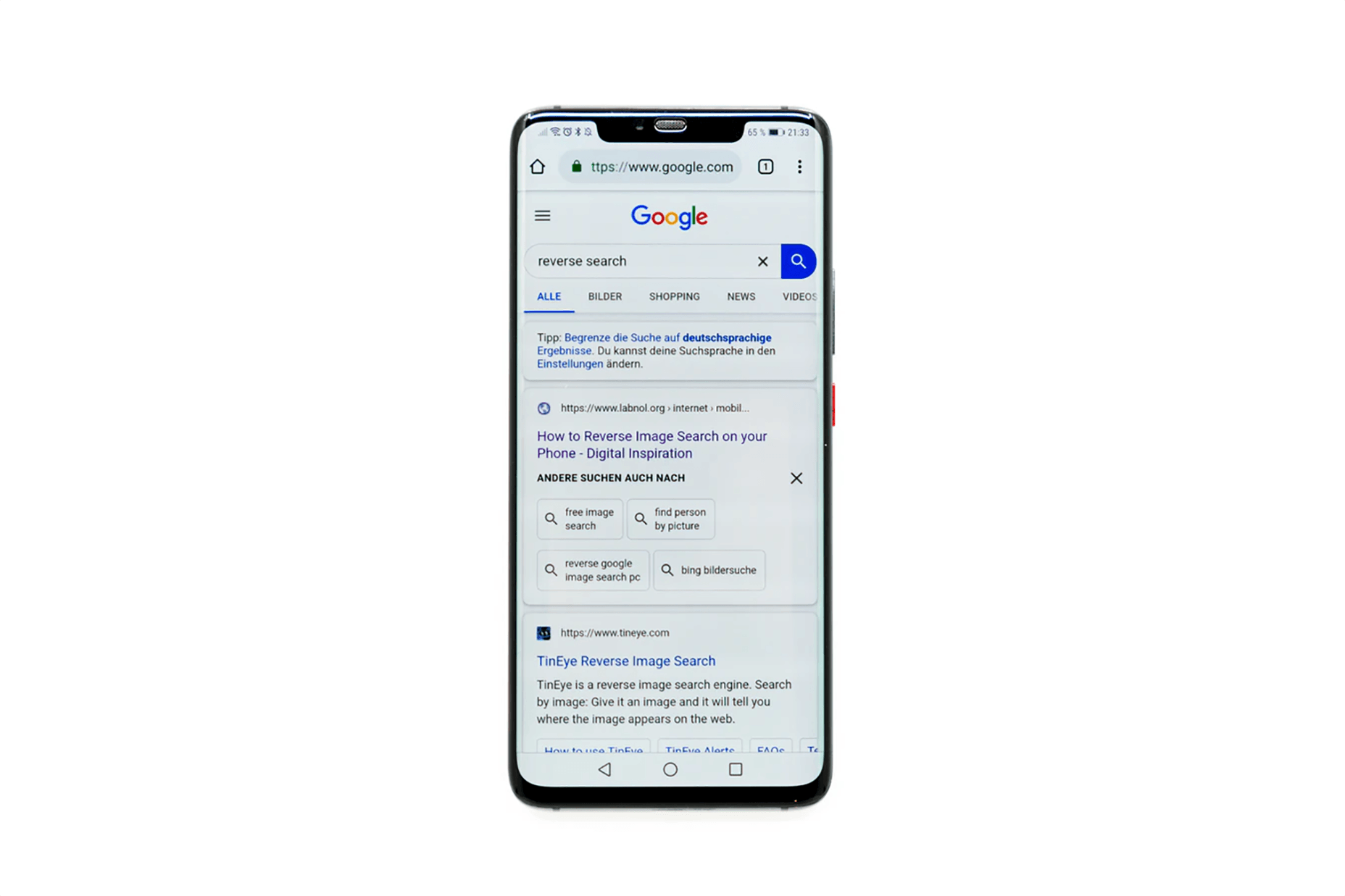
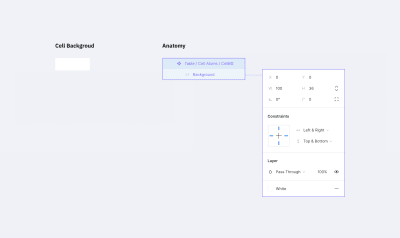
Changing the background color (Large preview)

Border

This one is a bit trickier than the background. You can’t just create one rectangle with a stroke. We may need different kinds of borders: one for the separate cells (with borders around), one for the whole row of cells with only top and bottom borders, or one for the table header that we might want to separate from the rest with a wider line. There are many options.

Border properties:

Border line (left, right, top, bottom, or absence of any of them)
Line width
Line color
Line style

Each line within the cell border might havea different width, color, and style. For example, the left one could be a continuous red line, and the top one a dotted grey line.

Let’s create a component with a size of 100×36 pixels (the same as we did before). Inside the component, we need to add 4 lines for each border. Now pay attention to how we are going to do this.

Add a line for the bottom border with the length of the component width;
Set its position to the bottom border and constraints to stretch horizontally and stick to the bottom border;
For the top border, duplicate the line for the bottom border, rotate it by 180 degrees and stick to the top of the component. (Don’t forget to change its constraints to stick to the top and stretch horizontally.);
Next, for the left border, simply rotate by -90 degrees and set its position and constraints to be at the left side sticking to the left border and stretching vertically;
Last but not least, you can create the right border by rotating it by 90 degrees and setting its position and constraints. Set stroke color and stroke width for each line to gray (select from the color styles) and 1 pixel respectively.

Note: You may be asking yourself why we rotated the line for the bottom border. Well, when you change the stroke width for a line in Figma, it will rise. So we had to set this “rise” direction to the center of the component. Changing the line’s stroke width (in our case it is the border size) won’t expand outside the component (cell).

Now we can hide or customize the styles separately for every border in the cell.

The Border Component

A border component with 1px stroke (Large preview)

If your project has several styles for table borders (a few border examples shown below), you should create a separate component for each style. Simply create a new master component as we did before and customize it the way you need.

Border Styles

A few extra examples of border styles. Note that the white background is not included in the component. (Large preview)

The separate stroke component will save up lots of your time and add scalability. If you change the stroke color inside the master component, the whole table will adjust. Same as with the background color above, each individual cell can have its own stroke parameters.

Border’s width and color
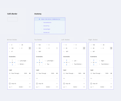
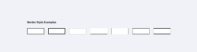
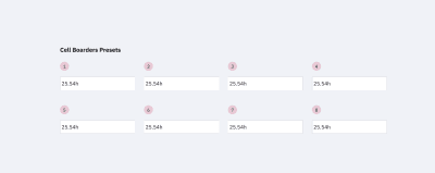
Changing border’s width and color (Large preview)

Content

This is the most complex component of all.

We need to create all possible variations of the table content in the project: plain text, a text with an icon (left or right, different alignment), checkboxes, switches, and any other content that a cell may possibly contain. To simplify this tutorial, please check the components in the mockup file. How to create and organize components in Figma is a topic for another article.

However, there are a few requirements for content components:

Components should stretch easily both vertically and horizontally to fit inside a cell;
The minimum size of the component should be less than the default cell size (especially height, keep in mind possible cell paddings);
Avoid any margins, so the components can align properly inside a cell;
Avoid unnecessary backgrounds because a cell itself has it already.

Content components examples

Examples of cell content in components. This is not a complete list; you can use most of the components of your design system inside a table. (Large preview)

Content components can be created gradually: start with the basic ones like text components and add new ones as the project grows in size.

The reason we want the content to be in components is the same as with other elements — it saves uptime. To change the cell’s content, we just need to switch it in the component.

Changing the component inside the cell
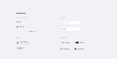
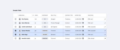
Editing the table using cells components (Large preview)

Creating A Cell Component

We created all the atoms we need: background, border, content. It’s time to create a cell component, i.e. the molecule made from atoms. Let’s gather all the components in a cell.

The cell component

The cell component (the ‘molecule’) (Large preview)

Set the background component as the bottom layer and stretch it to the whole cell size (set constraints to “Left & Right” and “Top & Bottom”).

Add the border component with the same constraints as the background component.

Now to the most complicated part — the content content.

The cell has paddings, so you need to make a frame with the component’s content. That frame should be stretched to the whole cell size except for the paddings. The content component should also be stretched to the whole frame size. The content itself needs to be deprived of any margins, so all paddings will be set by the cell.

At the end of the day, cell paddings are the only property in a component that we will set only once without an opportunity to change it later. In the example above, I made it 4px for all sides.

Note: As a fix, you can create columns with empty cells (with no content and width of 16px for example) left and right to the column where extra margin is needed. Or if your table’s design allows, you can add horizontal paddings inside the cell component. For example, cells in Google Material Design have 16px paddings by default.

Don’t forget to remove the “Clip content” option for the cell and frame (this can be done at the right-hand panel in the Properties section). The cell’s content can go out of its borders; for example, when a dropdown is inside your cell and you want to show its state with a popup.

Note: We’ll be using this cell style as the main one. Don’t worry if your table has additional styles — we’ll cover that in the Table States and Components, Not Overrides sections.

Cell Options For A Standard Table

This step could be optional but if your table needs states then you can’t go without it. And even more so if there is more than one border style in the table.

So let’s create additional cell components from which it’d be easier to build up a table. When working with a table, we will select the appropriate component depending on its position in the table (e.g. depending on the type of borders).

In order to do that, let’s take our cell component and create eight more masters from it. We also need to disable the appropriate layers responsible for borders. The result should look like the image below.

Cell options

The cell options we need to build a table. Note that there could be a few extra depending on your table borders styles. (Large preview)

The top row is for the cells on top and in the middle of the table. The bottom row is only for the cells at the bottom. This way we’ll be able to put the cells one after another with no gaps and keep the same stroke width.

A few examples:

The First example

If each cell in the table has a border, we’d only need cells 1, 4, 5 and 8. (Large preview)

The Second example

If there are merged cells or border absence, we must apply the rest 2 and 3 cells as well as 6 and 7 to the bottom row. (Large preview)

The Third example

If the table design considers the absence of vertical borders, cells 2 and 6 would be enough. (Large preview)

Note: For each border style created above, it’d be good to add master components like the ones described earlier.

So we have excluded the necessity of overriding cell’s instances (disabling the appropriate layers, to be precise). Instead of that, we use various components. Now if, for example, a column uses a different style from the default (the fill color or border), you can choose this column and simply change the relative component. And everything will be alright. On the opposite side, changing a border of each cell manually (disabling the appropriate borders) is a pain you don’t want to bother with.

Now we are ready to create tables (in terms of Atomic Design — organisms) from the various cell components (molecules) we made.

Customizing The Table

Changing the row’s height in the whole table is relatively easy: highlight the table, change the element height (in this case, the cell’s height, H in the right-hand panel in the Properties section), and then change the vertical margin from the element to 0. That’s it: changing the line height took two clicks!

Changing the row height
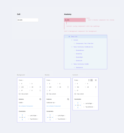
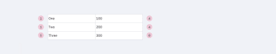
Changing the row height for the whole table (Large preview)

Changing the column width: highlight the column and change the width size. After moving the rest of the table close up, select the whole table by using the Tide Up option in the Alignment panel as well as the first item in the dropdown list under the rightmost icon.

Changing the column widthChanging the column width. (Large preview)

Note: I wouldn’t recommend grouping rows and columns. If you change the column size extending the elements, you’ll get fractional values for width and height. If you don’t group them and snap to the pixel grid, the cell size will remain an integer number.

The background color, stroke type, and content data can be changed in the appropriate component or in one of the eight cells master components (cells that had different stroke styles). The only parameter that can’t be changed right away is the cell margins, e.g. content paddings. The rest are easily customizable.

Components, Not Overrides

Looking at what we got in the end, it might seem like overkill. And it is if there is only one table in your project. In this case, you can simply create one cell component and leave the background and stroke components off. Simply include them in the cell component, create the table and do the necessary customization for each separate cell.

But if components are included in a library that is used by a number of other files, here comes the most interesting stuff.

Note: *I do not recommend changing the background color and stroke in components’ instances. Change them only in the master. By doing so, those instances with overrides won’t get updated. This means you would have to do that manually and that’s what we’re trying to avoid. So let’s stick to the master components.*

If we need to create an additional type of table cells (e.g. the table header), we add the necessary set of master components for cells with the appropriate styles (just like we did above with the eight cells that had different stroke styles), and use it. Yes, it takes longer than overriding components’ instances but this way you will avoid the case when changing the masters will apply those changes to all layouts.

Table States

Let’s talk about the states of the table’s elements. A cell can have three states: default, hover, and selected. Same for columns and rows.

If your project is relatively small, all states can be set by overrides inside instances of your table components. But if it’s a big one, and you’d want to be able to change the look of the states in the future, you’ll have to create separate components for everything.

You’ll need to add all eight cells with different stroke variants for each of the states (maybe less, depends on the stroke style). And yes, we’ll need separate components for the background color and the stroke for the states as well.

In the end, it’ll look similar to this:

Hover and Selected

The cells’ states (hover and selected) (Large preview)

Here’s where a bit of trouble comes in. Unfortunately, if we do everything as described above (when changing the component’s state from one to another), there is a risk of losing the cell’s content. We’ll have to update it apart from the case when the content type is the same as in the master cell. At this point, we can’t do anything about it.

Table with rows’ states

Table with various rows’ states. (Large preview)

I added tables in the mockup file that were made in a few different ways:

Using this tutorial (separate components for cells’ styles);
Using the cell component (components for borders, background, and content);
Using the cell component that unites everything (with only content components in addition).

Try to play around and change the cell’s styles.

Changing the state
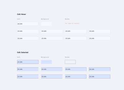
Changing the state of the row. (Large preview)

Conclusion

If you’re using the same components library in several projects and you’ve got a reasonable number of tables in each of them, you can create a local copy of components (cells components with stroke styles and, if needed, cells components with different states), customize them, and use them in the project. The cell content can be set based on local components.

Also, if you’re using the table for one large project with different kinds of tables, all the above-mentioned components are easily scaled. The table components can be improved to infinity and beyond, like creating the cell states when hovering and other kinds of interactions.

Questions, feedback, thoughts? Leave a comment below, and I’ll do my best to help you!

Figma Table Mockup Download

As promised, I created a complete version of the Figma table mockup that you’re welcome to use for learning purposes or anything else you like. Enjoy!

Tables in Figma mockup design

Here’s a Figma table mockup that you can use for learning purposes — let the creativity begin!

Related Reading

“Atomic Design,” Brad Frost
“How To Architect A Complex Web Table,” Slava Shestopalov, Smashing Magazine
“Creating Atomic Components In Figma,” Design & Engineering team, littleBits
“Figma Tables: Data Grid Design By A Single Cell-Component,” Roman Kamushken, Setproduct

Useful Resources

Figma YouTube Channel
The official Figma channel on YouTube — it’s the first thing to watch if you are new to Figma.
Google Sheets Sync
A Figma plugin that helps you get data from Google Sheets into your Figma file. This should work fine with the techniques from this tutoria, but you’ll need to invest some time into renaming all the text layers for this to work properly.

Smashing Editorial
(mb, yk, il)

Crafting Stylised Mouse Trails With OGL

Original Source: http://feedproxy.google.com/~r/tympanus/~3/aBOCpNSpPt0/

Mmm… swirly goodness…
Hey! Snap out of it! Ok. Now, in this tutorial we’re going to have some fun creating this pretty crazy little effect by tipping our toes into WebGL. The water is warm, I promise!

What’s OGL?

OGL is a WebGL library that is going to save us having to write a bunch of pretty unfriendly WebGL code directly. It has been my baby for the last year or so – I’ve been busy adding a bunch of examples to try and give people a kick-start with practical references.

By design, it’s tightly coupled to WebGL with only a small amount of abstraction – meaning it’s very lightweight. For example, the OGL classes required for this experiment are under 13kb gzipped – and more than half of them are just maths.

You got any more of them mouse trails?

Yes! Moving on, sorry.

Mouse trails (or any sort of trails) are just innately fun to interact with. The little touch of physics that it adds can really make an animation feel incredibly reactive and tangible, to the point where you can be certain that a good percentage of your users’ time will be spent playing with the effect, before consuming any of your site’s content… sorry not sorry.

Of course, they can be achieved using a whole range of techniques. Example time.

Starting with a really clever, recent one done using the DOM (html) and CSS. I especially love the difference-blend style they’ve added to the trail. The crux of the effect is a number of diminishing circles that follow one another, giving the effect of a tapered line.
Developed by Luca Mariotti. With the ink trail effect from Ricardo Mendieta.

Here’s an effective take on one, made using the 2D Canvas api. This one draws a circle at the head of each line every frame, while simultaneously the whole scene slowly disappears.
By Hakim El Hattab.

And here’s one used as a main game mechanic, made using SVG by yours truly – a few trips-around-the-sun ago… It’s a dynamic bezier curve whose start, middle and end positions are updated every frame.

So each of these previous (viable) options use drawing APIs (CSS, Canvas 2D, SVG) to render those pixels. WebGL, on the other hand, leaves all of that pixel-drawing math in your capable hands. This means two things.

Firstly, it’s more work for you. Yep, it’ll probably take you longer to get something up and running, working out those pesky projection matrices, while keeping an eye on the optimisation of your attribute buffers…

Buuut (important but), it’s less work for the computer – so it’ll run (normally, waaaay) faster. You’re basically cutting out the middle man. It also gives you a crazy amount of flexibility, which I highly appreciate.

The Approach

I’m a fan of visualising problems to understand them (let’s not talk about quaternions…), so let’s break it down.

We will start by making a number of points, made up of [x, y] coordinates, arranged in a lovely little line.

app-dots

Then we’ll use these to generate a geometry, duplicating each point so that there are two vertices at each step along the curve. Why two? Just a sec.

app-line

Now, because our paired points are at the exact same position, our line is infinitely thin when rendered – and hence, invisible… No good. What we need to do is separate those pairs to give the line some width. And, puuuush.

app-mesh

And there we have our line mesh, all visible and line-y…

The part I nimbly skipped over there is also the most complicated – how do we know in which direction to move each vertex?

To solve this, we need to work out the direction between the previous and next points along the line. Then we can rotate it by 90 degrees, and we’re left with the angle we want: the normal.

app-normal

Now that we have our normal, we can start getting a bit creative. For example, what if we separated the pairs differing amounts at each point? Here, if we make the pairs get closer together toward the ends of the line, it will give us this sharp, tapered effect.

app-taper

Now see what fun ideas you can come up with! I’ll wait. A bit more. Ok, stop.

And that’s the most complicated part over. Note: I haven’t gone into the depths of each caveat that drawing lines can present, because, well, I don’t need to. But I couldn’t possibly write about lines without mentioning this extremely informative and digestible article, written by Matt DesLauriers about everything you’d want to know about drawing lines in WebGL.

Code time – setting the scene

To kick us off, let’s set up a basic OGL canvas.

Here’s an OGL CodeSandbox Template project that I’ll be using as a guide. Feel free to fork this for any OGL experiments!

First import the required modules. Normally, I would import from a local copy of OGL for the ability to tree-shake, but to keep the file structure empty on CodeSandbox, here we’re using jsdelivr – which gives us CDN access to the npm deployment.

import {
Renderer, Camera, Orbit, Transform, Geometry, Vec3, Color, Polyline,
} from ‘https://cdn.jsdelivr.net/npm/ogl@0.0.25/dist/ogl.mjs’;

Create the WebGL context, and add the canvas to the DOM.

const renderer = new Renderer({dpr: 2});
const gl = renderer.gl;
document.body.appendChild(gl.canvas);

Create our camera and scene.

const camera = new Camera(gl);
camera.position.z = 3;

const controls = new Orbit(camera);

const scene = new Transform();

And then render the scene in an update loop. Obviously the scene is empty, so this will currently look very black.

function update(t) {
requestAnimationFrame(update);
controls.update();

renderer.render({scene, camera});
}

But now we can do all of the things!

As an input to OGL’s Polyline class, we need to create a bunch of points (xyz coordinates).

Here, the x value goes from -1.5 and 1.5 along the line, while the y value moves in a sine pattern between -0.5 and 0.5.

const count = 100;
const points = [];
for (let i = 0; i < count; i++) {
const x = (i / (count – 1) – 0.5) * 3;
const y = Math.sin(i / 10.5) * 0.5;
const z = 0;

points.push(new Vec3(x, y, z));
};

Then we pass those points into a new instance of Polyline, along with colour and thickness variables (uniforms). And finally, attach it to the scene.

const polyline = new Polyline(gl, {
points,
uniforms: {
uColor: {value: new Color(‘#1b1b1b’)},
uThickness: {value: 20},
},
});

polyline.mesh.setParent(scene);

Here we have that working live. (Click and drag, scroll etc. If you want…)

How about a square? Let’s just change those points.

const points = [];
points.push(new Vec3( 0, -1, 0));
points.push(new Vec3(-1, -1, 0));
points.push(new Vec3(-1, 1, 0));
points.push(new Vec3( 1, 1, 0));
points.push(new Vec3( 1, -1, 0));
points.push(new Vec3( 0, -1, 0));

Circle?

const count = 100;
const points = [];
for (let i = 0; i < count; i++) {
const angle = i / (count – 2) * Math.PI * 2;
const x = Math.cos(angle);
const y = Math.sin(angle);
const z = 0;

points.push(new Vec3(x, y, z));
};

You may have noticed that when you rotate or zoom the camera, the line will always stay the same thickness. You would probably expect the line to get thicker when it’s closer to to camera, and also to be paper thin when rotated on its side.

This is because the pair separation we spoke about earlier is happening after the camera’s projection is applied – when the vertex values are in what’s called ‘NDC Space’ (Normalized Device Coordinates). Projection matrices can be confusing, but luckily, NDC Space is not.

NDC Space is simply picturing your canvas as a 2D graph, with left to right (X), and bottom to top (Y) going from -1 to 1. No matter how complicated your scene is (geometry, projections, manipulations), each vertex will eventually need to be projected to a -1 to 1 range for X and Y.

code-screen

A more common term you’ve probably heard is Screen Space, which is very similar, but instead of a -1 to 1 range, it’s mapped from 0 to 1.

We generally use cameras to help us convert our 3D coordinates into NDC Space, which is absolutely vital when you need to spin around an object, or view geometry from a specific perspective. But for what we’re doing (mouse trails. I haven’t forgotten), we don’t really need to do any of that! So, in fact, we’re going to skip that whole step, throw away the camera, and create our points directly in NDC Space (-1 to 1) from the get-go. This simplifies things, and it also means that we’re going to get the opportunity to write a custom shader! Let me show you.

Shaping the line with a custom shader

Firstly, let’s create our points in a straight line, with the X going from -0.5 to 0.5 and the Y left at 0. Keeping in mind that the screen goes from -1 to 1, this means we will end up with a horizontal line in the center of the screen, spanning half the width.

const count = 40;
const points = [];
for (let i = 0; i < count; i++) {
const x = i / (count – 1) – 0.5;
const y = 0;
const z = 0;

points.push(new Vec3(x, y, z));
};

This time when we create our Polyline, we are going to pass in a custom Vertex shader, which will override the default shader found in that class. We also don’t need a thickness just yet as we’ll be calculating that in the shader.

const polyline = new Polyline(gl, {
points,
vertex,
uniforms: {
uColor: {value: new Color(‘#1b1b1b’)},
},
});

Now, there are two shaders in the WebGL pipeline, Vertex and Fragment. To put it simply, the Vertex shader determines where on the screen to draw, and the Fragment shader determines what colour.

We can pass into a Vertex shader whatever data we want, that’s entirely up to you. However, it will always be expected to return a position on the viewport that should be rendered (in Clip Space, which, for this case, is the same as NDC Space; -1 to 1).

At the start of our Vertex shader, you will find the input data: Attributes and Uniforms. Attributes are per-vertex variables, whereas Uniforms are common variables for all of the vertices. For example, as this shader is run for each vertex passed in, the position Attribute value will change, moving along each point, however the uResolution Uniform value will remain the same throughout.

attribute vec3 position;
attribute vec3 next;
attribute vec3 prev;
attribute vec2 uv;
attribute float side;

uniform vec2 uResolution;

At the very end of our Vertex shader, you’ll find a function called main that defines the variable gl_Position. These two names are non-debatable! Our WebGL program will automatically look for the main function to run, and then it will pass the gl_Position variable on to the Fragment shader.

void main() {
gl_Position = vec4(position, 1);
}

As our points are already in NDC Space, our shader – made up of just these two sections – is technically correct. However the only issue (the same as we had in our breakdown) is that the position pairs are on top of each other, so our line would be invisibly thin.

So instead of passing our position right on through to the output, let’s add a function, getPosition, to push each vertex apart and give our line some width.

vec4 getPosition() {
vec2 aspect = vec2(uResolution.x / uResolution.y, 1);
vec2 nextScreen = next.xy * aspect;
vec2 prevScreen = prev.xy * aspect;

vec2 tangent = normalize(nextScreen – prevScreen);
vec2 normal = vec2(-tangent.y, tangent.x);
normal /= aspect;
normal *= 0.1;

vec4 current = vec4(position, 1);
current.xy -= normal * side;
return current;
}

void main() {
gl_Position = getPosition();
}

Ah, now we can see our line. Mmmm, very modernist.

This new function is doing the exact steps in our approach overview. See here.

We determine the direction from the previous to the next point.

vec2 tangent = normalize(nextScreen – prevScreen);

Then rotate it 90 degrees to find the normal.

vec2 normal = vec2(-tangent.y, tangent.x);

Then we push our vertices apart along the normal. The side variable has a value of -1 or 1 for each side of a pair.

current.xy -= normal * side;

“OK OK… but you skipped a few lines”.

Indeed. So, the lines that determine and apply the aspect ratio are there to account for the rectangular viewport. Multiplying against the aspect ratio makes our scene square. Then we can perform the rotation without risk of skewing. And after, we divide by the aspect to bring us back to the correct ratio.

And the other line…

normal *= 0.1;

Yes that one… is where we can have some fun. As this manipulates the line’s width.

Without this bit of code, our line would cover the entire height of the viewport. Why? See if you can guess…

You see, as the normal is a ‘normalised’ direction, this means it has a length of 1. As we know, the NDC Space goes from -1 to 1, so if our line is in the middle of the screen, and each side of the line is pushed out by 1, that will cover the entire range of -1 to 1. So multiplying by 0.1 instead only makes our line cover 10% of the viewport.

Now if we were to change this line, to say…

normal *= uv.y * 0.2;

We get this expanding, triangular shape.

width-01

This is because the variable uv.y goes from 0 to 1 along the length of the line. So we can use this to affect the shape in a bunch of different ways.

Like, we can wrap that code in a pow function.

normal *= pow(uv.y, 2.0) * 0.2;

width-02

Hm, how exponentially curvy. No, I want something more edgy.

normal *= abs(fract(uv.y * 2.0) – 0.5) * 0.4;

width-03

Too edgy…

normal *= cos(uv.y * 12.56) * 0.1 + 0.2;

width-04

Too flabby.

normal *= (1.0 – abs(uv.y – 0.5) * 2.0) * 0.2;

width-05

Almost… but a little too diamond-y.

normal *= (1.0 – pow(abs(uv.y – 0.5) * 2.0, 2.0)) * 0.2;

width-06

That’s not bad. Let’s run with that.

So now we have our shape, let’s deal with the movement.

Adding movement

To start off we just need 20 points, left at the default [0, 0, 0] value.

Then we need a new Vec3 that will track the mouse input, and covert the X and Y values to a -1 to 1 range, with the Y flipped.

const mouse = new Vec3();

function updateMouse(e) {
mouse.set(
(e.x / gl.renderer.width) * 2 – 1,
(e.y / gl.renderer.height) * -2 + 1,
0
);
}

Then in our update function, we can use this mouse value to move our points.

Every frame, we loop through each of our points. For the first point, we ease it to the mouse value. For every other point, we ease it to the previous point in the line. This creates a trail effect, that grows and shrinks as the user moves the mouse faster and slower.

requestAnimationFrame(update);
function update(t) {
requestAnimationFrame(update);

for (let i = points.length – 1; i >= 0; i–) {
if (!i) {
points[i].lerp(mouse, 0.9);
} else {
points[i].lerp(points[i – 1], 0.9);
}
}
polyline.updateGeometry();

renderer.render({scene});
}

Have a play with it below.

We can make this a bit more fun by replacing the first point’s linear easing with a spring.

const spring = 0.06;
const friction = 0.85;
const mouseVelocity = new Vec3();
const tmp = new Vec3();

requestAnimationFrame(update);
function update(t) {
requestAnimationFrame(update);

for (let i = points.length – 1; i >= 0; i–) {
if (!i) {
tmp.copy(mouse).sub(points[i]).multiply(spring);
mouseVelocity.add(tmp).multiply(friction);
points[i].add(mouseVelocity);
} else {
points[i].lerp(points[i – 1], 0.9);
}
}
polyline.updateGeometry();

renderer.render({scene});
}

The extra bit of physics just makes it that much more interesting to play with. I can’t help but try and make a beautiful curving motion with the mouse…

Finally, one line is never enough. And what’s with all of this dark grey?! Give me 5 coloured lines, with randomised spring values, and we’ll call it even.

And there we have it!

As we’re using random values, every time you refresh, the effect will behave a little differently.

End

Thank you so much for sticking with me. That ended up being a lot more in-depth than I had planned… I implore you to play around with the code, maybe try randomising the number of points in each line… or changing the shape of the curve over time!

If you’re new to WebGL, I hope this made the world of buffer attributes and shaders a little less overwhelming – it can be really rewarding to come up with something interesting and unique.

Crafting Stylised Mouse Trails With OGL was written by Nathan Gordon and published on Codrops.

Illustrator Sebastian Curi on colour, character design and keeping things fun

Original Source: http://feedproxy.google.com/~r/CreativeBloq/~3/D0yQ1iBd_8k/illustrator-sebastian-curi-on-colour-character-design-and-keeping-things-fun

You may have been to a design conference before. But have you ever been to one that starts when the sun goes down? 

That's the secret ingredient behind Us by Night which takes place in the evening, leading to a special different atmosphere, that's markedly different from other creative events. 

Taking place in Antwerp, Belgium this Thursday, Friday and Saturday (26-28 September), Us by Night is packed with fun activities, including an arcade, a night market, a delicious selection of local food, and fluorescent ping-pong.

But of course, the main attractions are the briliant and inspirational speakers from across the world, and one of the top attractions this year will be the return of Sebastian Curi. 

Who is Sebastian Curi?

Sebastian Curi is an Argentinian illustrator and animator, currently based in Vancouver, who's known for his fun characters and bold illustration style, characterised by strong lines, big shapes and simple colour palettes.

Artwork

Illustration for mobile payment service Venmo by Sebastian Curi

Having spent a decade working in the animation industry, he's recently switched his main focus to illustration, working with a variety of agencies, clients and artists including Apple, Warby Parker, Collins, The New Yorker, IDEO, WeWork, CNN, Soul Cycle and others.

We caught up with him to find out what he'll be talking about at Us by Night, and why you shouldn't miss his talk.

How did growing up in Argentina influence your work?

I’m from Buenos Aires. Growing up, my parents moved a lot around the province in search of better job opportunities so I’m not really from any neighborhood. I started working when I was studying in high school and, as my family had little money, my creative development moved slowly until I reached a job in a graphic design studio. 

Argentina is a country of contradictions and instability. As a by-product of that, you learn how to deal with lots of things at the same time. 

In my case that involved studying and working at the same time and working in different positions around the design and animation industry, until I found what I liked. Kind of a jack of all trades, master of none situation.   

How did you come to live in Canada?

After working for some years in different studios in Buenos Aires, I went freelance as an animator. At some point I felt really stuck with my career, and sent a couple emails to studios in the world that I liked. 

Amazingly, I got an offer from a big production company in Los Angeles, and that started a whole different stage for me. LA is an amazing city but travelling the world seemed such an exciting thing to do. 

Illustration of woman running with dog

Outdoor Voices 1 by Sebastian Curi

After two years at this production company, I didn’t feel connected to my work and my illustration stuff was still something that I thought as a side job. 

So I went looking for a smaller and more cosy studio and that’s how I arrived at Vancouver, Canada to work at Giant Ant.

Was your recent move from animation to illustration an easy one?

I worked in animation for 10 years and leaving that was a very hard move to make. I was very hesitant, and because of that I kept working on studios until I was completely sure I could sustain myself and my wife without problems. 

That also created its own problems. Having two jobs put me in a place of lots of stress, little time and all of that impacted in my health a lot.

It took me more than a year of working every morning or night, and putting some weekends into my illustration stuff, to feel that I have something interesting to bring to the industry.

I finally moved into illustration because I feel I can have more ownership of my work as an illustrator. I love the freedom I have to work, how clients move in this industry, the time it takes me to finish a project. Every little thing about illustration seems magical to my “animator eyes”.

Is it important that you create characters with flaws? 

I’m all about bold and simple drawings. I like the spontaneity of my process and how they lead to joyful and lively results. 

For me, illustration is a way to create moments and have some fun, and this people I draw are perfect for conveying the things I want to say.

Three colourful cartoon characters and a dog

Illustration for mobile payment service Venmo by Sebastian Curi

In the beginning, the imperfections in my drawings were due to a lack of ability to draw perfectly. But at some point I fell in love with the textures and handmade vibe they give overall… so I stuck to them.

How much do you collaborate with others?

I love to collaborate. You are as good as the people you work with, and I really like to work with people that I can learn from. 

Lately, I’ve been doing a lot of animation with some amazing animators. Also, I worked a week on a huge mural for the Vancouver Mural Fest.

I would say collaborating is the only thing I really miss from animation. Illustration can be a bit lonely.

What’s your approach to colour? 

For me, colours have beauty in themselves. It’s all about proportion and vibration. I prefer to work with big shapes and just let the colours do their thing. 

Illustration of person holding a rainbow between their palms

Outdoor Voices 2 by Sebastian Curi

I usually tend to start with high vibration colours in big sizes and then I just add details of lines and patterns with low saturation colours. It’s never the same, I like some combinations but I try to keep things fun at this stage.

Colour gives you the tone of the story. It creates the context.

What are you speaking about at Us by Night?

This is my first talk at a design festival so I’m pretty nervous about it. I love to attend these kind of events, listen to podcasts and read about the industry – but saying something that helps people or brings value is a challenging thing to do.

Sebastian Curi's work on big screen in conference centre

On show at Apple Today

My talk is going to be about changing over time in search of keeping it fun. How to find something you love and make it a job but in a healthy and sustainable way. Basically, it will focus on my journey, how each step took me to where I’m at now.

Us by Night takes place at Antwerp, Belgium from Thursday September 26, 2019 – Saturday September 28, 2019.


Tips On Designing Creative Websites That Will Wow Your Clients

Original Source: https://www.webdesignerdepot.com/2019/09/tips-on-designing-creative-websites-that-will-wow-your-clients/

The global market keeps getting bigger and bigger, which should be good news for web designers – but there’s a catch.

The clients you can expect to serve are more sophisticated and want creative websites, not just the regular HTML and CSS.

You can’t deliver just anything and expect them to be happy. You’ll also have some serious competition to contend with. As a consequence, your website must adequately address an ever-growing need for improvements. Like in flexibility, responsiveness, and conversion optimization.

Fortunately, the cloud has a silver lining; and a bright one at that. Tools to meet these challenges and address them head on are readily available. With the most notable case in point being Be Theme, the largest and most versatile WordPress theme of them all.

With a tool like Be Theme at your fingertips, you’ll be more than able to successfully handle any challenge that comes your way.

Then, it’s simply a matter of following these 5 simple steps to design creative websites. They are eye-catching, impressive in their ability to convert visitors to users and guaranteed to put smiles on your clients’ faces.

5 Steps to Building Astoundingly Creative Websites
Step 1: Choose a Mesmerizing Color Palette

The color palette you use can make a difference between a so-so website and an attention-getting one. Choosing one should not be difficult if you follow a few simple rules:

its colors need to attract instant attention;
they need to be on-brand, and;
the color palette you select needs to visually support the message your app or website is designed to convey

Artist features BOLD color touches that will instantly attract attention.

This Be Theme pre-built website is another great example of what can be accomplished with an eye-grabbing color palette.

Carbon8 is an example of how to align the color palette with the website’s brand. It is done with its clever use of various shades of green. Note how the deep green element draws visitor’s eyes to the center of the page.

BeInsurance features a subtle, crisp color palette. It perfectly reinforces a strategy of using crisp, clear images to gain the clients you need.

BeFestival is a great example of using a color palette designed to appeal to a larger audience.

Step 2: Display Crystal-Clear Photos and Images

This step should be obvious. A crystal clear presentation suggests the business behind it goes the extra mile. That is when it comes to clearly present their products and services. Using the best images you can get your hands on can give you an extra edge over the competition.

BeStylist is an example of the advantage of displaying images with flair. The crisp image definitely supports the intended message.

Or, try something like RansomLTD; minimalist, yet crisp and powerful.

A pre-built website like Zajno illustrates how crystal-clear pics can be used to display your creativity.

The Design Shop employs flair and creativity to entice visitors with crisp and compelling images of your products.

Step 3: Show Visitors How Your Creativity Benefits Them

Creativity isn’t about you. It’s about serving your visitors. It can be extremely effective when it helps them imagine themselves actually using your product or service.

BeMarketing’s homepage video illustrates another way to show people how they can benefit from using your products.

Lane illustrates a fabulous approach you can use to express your structural design perspectives.

BeSimple takes a minimalist approach. It’s the typography and way the text is presented rather than the text itself that’s effective.

BeTravelBlogger provides the basis for a travel blogger’s dream site. You can use it to present your travel adventures and escapades with a super-cool layout of graphics and snippets.

Step 4: (Over)use “White” Space

Yes, it’s true. White space is a design element you can sometimes overuse without causing harm. In fact, in many cases “more is better”, as is obvious in the following examples.

Makespace has a clean design that allows the eye to focus on key elements, imagine, and create.

BeSketch & The Drive New York are two examples where plenty of white space is used to great effect.

When white space is part of the brand it can really help to drive the message home. BeIcecream is an extreme example of how plenty of white space can be used to great effect.

Step 5: Make Your CTAs Grab Them By The Eyeballs

If you don’t have CTA buttons that can’t be ignored, your website isn’t going to convert as many visitors into users as you hoped or planned. You want those buttons to be big, bright, and bold enough to make people feel they absolutely have to be clicked on.

BeDrawing’s CTA button is above the fold as it should be, and it clearly stands out. You can’t help but notice it the instant you’ve finished reading the headline. Its centering on the page makes it serve as a gate that invites visitors to enter.

Stuart makes effective placement and use of 3 clearly defined CTA buttons.

Your CTA can match other elements on the page and still easily attract attention. A great example of this is BeKids, where the color of the button matches the color of other hero section elements.

Building Creative Websites – a Summary

Follow these surefire steps (with the help of a surefire website building tool) and you’re well on your way to satisfying the most demanding of clients. Crisp, stunning visuals, a cleverly chosen color palette and the clever use of white space, images that enable visitors to see themselves using your products, and the all-important bold and beautiful CTA buttons give you the combination for success.

Success typically breeds additional work. Sometimes web design is not as much fun as it used to be. If you suddenly find yourself juggling projects and deadlines to the point you’d be better off using pre-built websites.

You’ll find the most generous gallery of more than 450 creative websites on Be Theme that you can customize to your liking. Start using them now and you’ll never have to worry about juggling projects and deadlines!


[– This is a sponsored post on behalf of Be Theme –]

Source

p img {display:inline-block; margin-right:10px;}
.alignleft {float:left;}
p.showcase {clear:both;}
body#browserfriendly p, body#podcast p, div#emailbody p{margin:0;}