Creating Tables In Figma
Original Source: https://www.smashingmagazine.com/2019/09/creating-tables-in-figma/
Creating Tables In Figma
Creating Tables In Figma
Sasha Belichenko
2019-09-25T12:30:59+02:00
2019-09-25T17:05:50+00:00
In this tutorial, we will talk about how tables can be created in Figma by using components and Atomic Design methodology. We will also take a look at the basic elements of the table layout and how components can be included in the component library so that they can become part of the design system you are using.
To make it easy for you, I’ve prepared a mockup example that uses all of the components we need for this tutorial.
To follow along, you will need to have at least some understanding of the basic Figma concepts, its interface, and how to work with Figma components. However, if you’re new to Figma and working with table data, I recommend watching the “Getting Started” video to help you better understand Figma end-to-end, as well as the article “How To Architect A Complex Web Table” that was published not too long ago here on Smashing Magazine.
To simplify the scope of this tutorial, let’s assume that the colors, fonts, and effects already exist as styles in the Figma project you’re about to begin. In terms of Atomic Design, they are atoms. (To learn more, the folks at littleBits wrote a great article on the topic.)
The target audience for this tutorial are designers (UX, UI) who have either already adopted Figma into their workflows or are planning to try Figma in their next design projects but aren’t sure how to get started.
So, without further ado, let’s dig in!
Quick Note: While writing this article, Figma introduced plugins. At the time of publishing, there weren’t any good ones for working with tables, but things might change fast. Who knows, maybe this article will actually help an aspiring Figma plugin developer to create a really neat Figma Tables plugin, or at least, I hope it will. ?
Introduction
Imagine the table as an organism. The table cell is then a molecule which is comprised of individual atoms. In design terms, they’re cell properties.
So, let’s start with the cell. It has three properties:
Background
Border
Content
Now we’ll take a closer look at each one of them.
Background
The background will be a separate component in Figma. The size doesn’t really matter since we can stretch the component as we need, but let’s begin with setting the size to 100×36 pixels.
In this component, add a rectangle of the same size as the component itself. It will be the only object inside the component. We need to attach the rectangle’s borders to the component’s borders by using constraints (set constraints to “Left & Right” and “Top & Bottom” at the right panel in the Constraints section), so that the rectangle stretches automatically to the size of the component.
If you’d like to see this in action, watch this tutorial on how the constraints work in Figma.
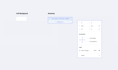
The Background Component (the ‘atom’) (Large preview)
The fill color of the rectangle will determine the background color of the cell. Let’s pick the white color for it. I recommend choosing that color from the color styles that are configured at the beginning of the project.
 Changing the background color (Large preview)
Border
This one is a bit trickier than the background. You can’t just create one rectangle with a stroke. We may need different kinds of borders: one for the separate cells (with borders around), one for the whole row of cells with only top and bottom borders, or one for the table header that we might want to separate from the rest with a wider line. There are many options.
Border properties:
Border line (left, right, top, bottom, or absence of any of them)
Line width
Line color
Line style
Each line within the cell border might havea different width, color, and style. For example, the left one could be a continuous red line, and the top one a dotted grey line.
Let’s create a component with a size of 100×36 pixels (the same as we did before). Inside the component, we need to add 4 lines for each border. Now pay attention to how we are going to do this.
Add a line for the bottom border with the length of the component width;
Set its position to the bottom border and constraints to stretch horizontally and stick to the bottom border;
For the top border, duplicate the line for the bottom border, rotate it by 180 degrees and stick to the top of the component. (Don’t forget to change its constraints to stick to the top and stretch horizontally.);
Next, for the left border, simply rotate by -90 degrees and set its position and constraints to be at the left side sticking to the left border and stretching vertically;
Last but not least, you can create the right border by rotating it by 90 degrees and setting its position and constraints. Set stroke color and stroke width for each line to gray (select from the color styles) and 1 pixel respectively.
Note: You may be asking yourself why we rotated the line for the bottom border. Well, when you change the stroke width for a line in Figma, it will rise. So we had to set this “rise” direction to the center of the component. Changing the line’s stroke width (in our case it is the border size) won’t expand outside the component (cell).
Now we can hide or customize the styles separately for every border in the cell.
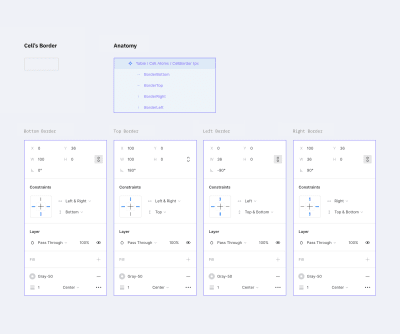
A border component with 1px stroke (Large preview)
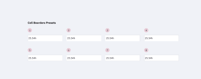
If your project has several styles for table borders (a few border examples shown below), you should create a separate component for each style. Simply create a new master component as we did before and customize it the way you need.
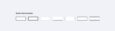
A few extra examples of border styles. Note that the white background is not included in the component. (Large preview)
The separate stroke component will save up lots of your time and add scalability. If you change the stroke color inside the master component, the whole table will adjust. Same as with the background color above, each individual cell can have its own stroke parameters.
 Changing border’s width and color (Large preview)
Content
This is the most complex component of all.
We need to create all possible variations of the table content in the project: plain text, a text with an icon (left or right, different alignment), checkboxes, switches, and any other content that a cell may possibly contain. To simplify this tutorial, please check the components in the mockup file. How to create and organize components in Figma is a topic for another article.
However, there are a few requirements for content components:
Components should stretch easily both vertically and horizontally to fit inside a cell;
The minimum size of the component should be less than the default cell size (especially height, keep in mind possible cell paddings);
Avoid any margins, so the components can align properly inside a cell;
Avoid unnecessary backgrounds because a cell itself has it already.
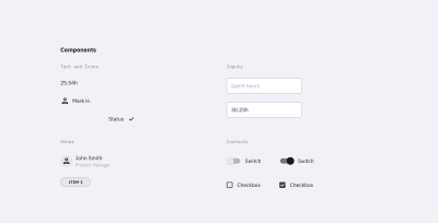
Examples of cell content in components. This is not a complete list; you can use most of the components of your design system inside a table. (Large preview)
Content components can be created gradually: start with the basic ones like text components and add new ones as the project grows in size.
The reason we want the content to be in components is the same as with other elements — it saves uptime. To change the cell’s content, we just need to switch it in the component.
 Editing the table using cells components (Large preview)
Creating A Cell Component
We created all the atoms we need: background, border, content. It’s time to create a cell component, i.e. the molecule made from atoms. Let’s gather all the components in a cell.
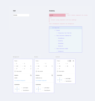
The cell component (the ‘molecule’) (Large preview)
Set the background component as the bottom layer and stretch it to the whole cell size (set constraints to “Left & Right” and “Top & Bottom”).
Add the border component with the same constraints as the background component.
Now to the most complicated part — the content content.
The cell has paddings, so you need to make a frame with the component’s content. That frame should be stretched to the whole cell size except for the paddings. The content component should also be stretched to the whole frame size. The content itself needs to be deprived of any margins, so all paddings will be set by the cell.
At the end of the day, cell paddings are the only property in a component that we will set only once without an opportunity to change it later. In the example above, I made it 4px for all sides.
Note: As a fix, you can create columns with empty cells (with no content and width of 16px for example) left and right to the column where extra margin is needed. Or if your table’s design allows, you can add horizontal paddings inside the cell component. For example, cells in Google Material Design have 16px paddings by default.
Don’t forget to remove the “Clip content” option for the cell and frame (this can be done at the right-hand panel in the Properties section). The cell’s content can go out of its borders; for example, when a dropdown is inside your cell and you want to show its state with a popup.
Note: We’ll be using this cell style as the main one. Don’t worry if your table has additional styles — we’ll cover that in the Table States and Components, Not Overrides sections.
Cell Options For A Standard Table
This step could be optional but if your table needs states then you can’t go without it. And even more so if there is more than one border style in the table.
So let’s create additional cell components from which it’d be easier to build up a table. When working with a table, we will select the appropriate component depending on its position in the table (e.g. depending on the type of borders).
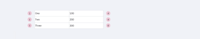
In order to do that, let’s take our cell component and create eight more masters from it. We also need to disable the appropriate layers responsible for borders. The result should look like the image below.
The cell options we need to build a table. Note that there could be a few extra depending on your table borders styles. (Large preview)
The top row is for the cells on top and in the middle of the table. The bottom row is only for the cells at the bottom. This way we’ll be able to put the cells one after another with no gaps and keep the same stroke width.
A few examples:
If each cell in the table has a border, we’d only need cells 1, 4, 5 and 8. (Large preview)
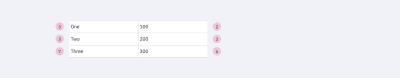
If there are merged cells or border absence, we must apply the rest 2 and 3 cells as well as 6 and 7 to the bottom row. (Large preview)
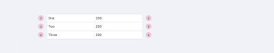
If the table design considers the absence of vertical borders, cells 2 and 6 would be enough. (Large preview)
Note: For each border style created above, it’d be good to add master components like the ones described earlier.
So we have excluded the necessity of overriding cell’s instances (disabling the appropriate layers, to be precise). Instead of that, we use various components. Now if, for example, a column uses a different style from the default (the fill color or border), you can choose this column and simply change the relative component. And everything will be alright. On the opposite side, changing a border of each cell manually (disabling the appropriate borders) is a pain you don’t want to bother with.
Now we are ready to create tables (in terms of Atomic Design — organisms) from the various cell components (molecules) we made.
Customizing The Table
Changing the row’s height in the whole table is relatively easy: highlight the table, change the element height (in this case, the cell’s height, H in the right-hand panel in the Properties section), and then change the vertical margin from the element to 0. That’s it: changing the line height took two clicks!
 Changing the row height for the whole table (Large preview)
Changing the column width: highlight the column and change the width size. After moving the rest of the table close up, select the whole table by using the Tide Up option in the Alignment panel as well as the first item in the dropdown list under the rightmost icon.
 Changing the column width. (Large preview)
Note: I wouldn’t recommend grouping rows and columns. If you change the column size extending the elements, you’ll get fractional values for width and height. If you don’t group them and snap to the pixel grid, the cell size will remain an integer number.
The background color, stroke type, and content data can be changed in the appropriate component or in one of the eight cells master components (cells that had different stroke styles). The only parameter that can’t be changed right away is the cell margins, e.g. content paddings. The rest are easily customizable.
Components, Not Overrides
Looking at what we got in the end, it might seem like overkill. And it is if there is only one table in your project. In this case, you can simply create one cell component and leave the background and stroke components off. Simply include them in the cell component, create the table and do the necessary customization for each separate cell.
But if components are included in a library that is used by a number of other files, here comes the most interesting stuff.
Note: *I do not recommend changing the background color and stroke in components’ instances. Change them only in the master. By doing so, those instances with overrides won’t get updated. This means you would have to do that manually and that’s what we’re trying to avoid. So let’s stick to the master components.*
If we need to create an additional type of table cells (e.g. the table header), we add the necessary set of master components for cells with the appropriate styles (just like we did above with the eight cells that had different stroke styles), and use it. Yes, it takes longer than overriding components’ instances but this way you will avoid the case when changing the masters will apply those changes to all layouts.
Table States
Let’s talk about the states of the table’s elements. A cell can have three states: default, hover, and selected. Same for columns and rows.
If your project is relatively small, all states can be set by overrides inside instances of your table components. But if it’s a big one, and you’d want to be able to change the look of the states in the future, you’ll have to create separate components for everything.
You’ll need to add all eight cells with different stroke variants for each of the states (maybe less, depends on the stroke style). And yes, we’ll need separate components for the background color and the stroke for the states as well.
In the end, it’ll look similar to this:
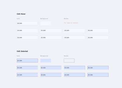
The cells’ states (hover and selected) (Large preview)
Here’s where a bit of trouble comes in. Unfortunately, if we do everything as described above (when changing the component’s state from one to another), there is a risk of losing the cell’s content. We’ll have to update it apart from the case when the content type is the same as in the master cell. At this point, we can’t do anything about it.
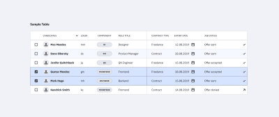
Table with various rows’ states. (Large preview)
I added tables in the mockup file that were made in a few different ways:
Using this tutorial (separate components for cells’ styles);
Using the cell component (components for borders, background, and content);
Using the cell component that unites everything (with only content components in addition).
Try to play around and change the cell’s styles.
 Changing the state of the row. (Large preview)
Conclusion
If you’re using the same components library in several projects and you’ve got a reasonable number of tables in each of them, you can create a local copy of components (cells components with stroke styles and, if needed, cells components with different states), customize them, and use them in the project. The cell content can be set based on local components.
Also, if you’re using the table for one large project with different kinds of tables, all the above-mentioned components are easily scaled. The table components can be improved to infinity and beyond, like creating the cell states when hovering and other kinds of interactions.
Questions, feedback, thoughts? Leave a comment below, and I’ll do my best to help you!
Figma Table Mockup Download
As promised, I created a complete version of the Figma table mockup that you’re welcome to use for learning purposes or anything else you like. Enjoy!
Here’s a Figma table mockup that you can use for learning purposes — let the creativity begin!
Related Reading
“Atomic Design,” Brad Frost
“How To Architect A Complex Web Table,” Slava Shestopalov, Smashing Magazine
“Creating Atomic Components In Figma,” Design & Engineering team, littleBits
“Figma Tables: Data Grid Design By A Single Cell-Component,” Roman Kamushken, Setproduct
Useful Resources
Figma YouTube Channel
The official Figma channel on YouTube — it’s the first thing to watch if you are new to Figma.
Google Sheets Sync
A Figma plugin that helps you get data from Google Sheets into your Figma file. This should work fine with the techniques from this tutoria, but you’ll need to invest some time into renaming all the text layers for this to work properly.
![]()
(mb, yk, il)


Leave a Reply
Want to join the discussion?Feel free to contribute!